Assembly Videos
Select a product below to view assembly instructions

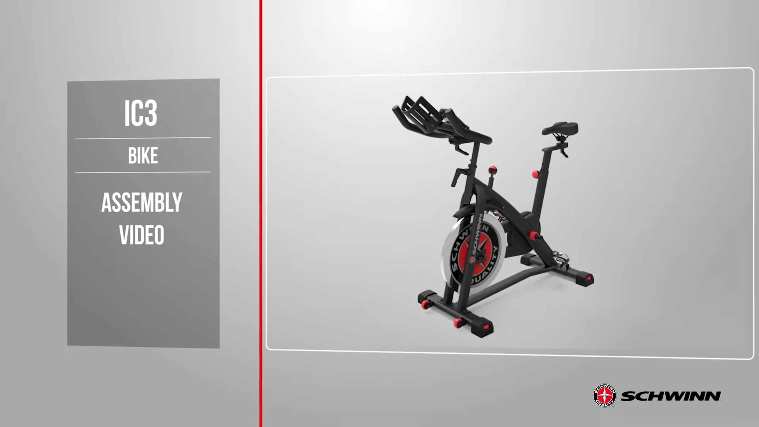
IC Bikes

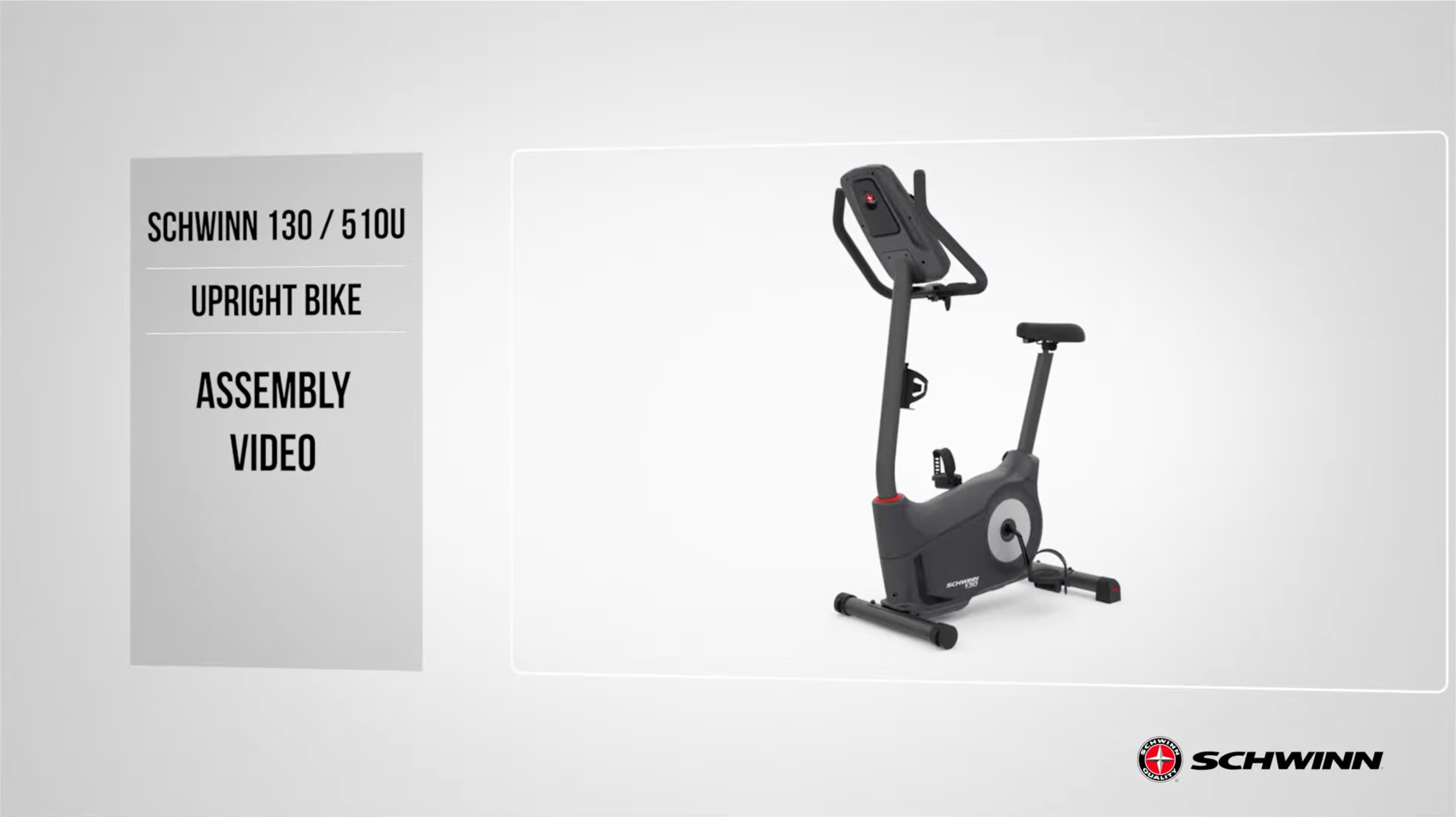
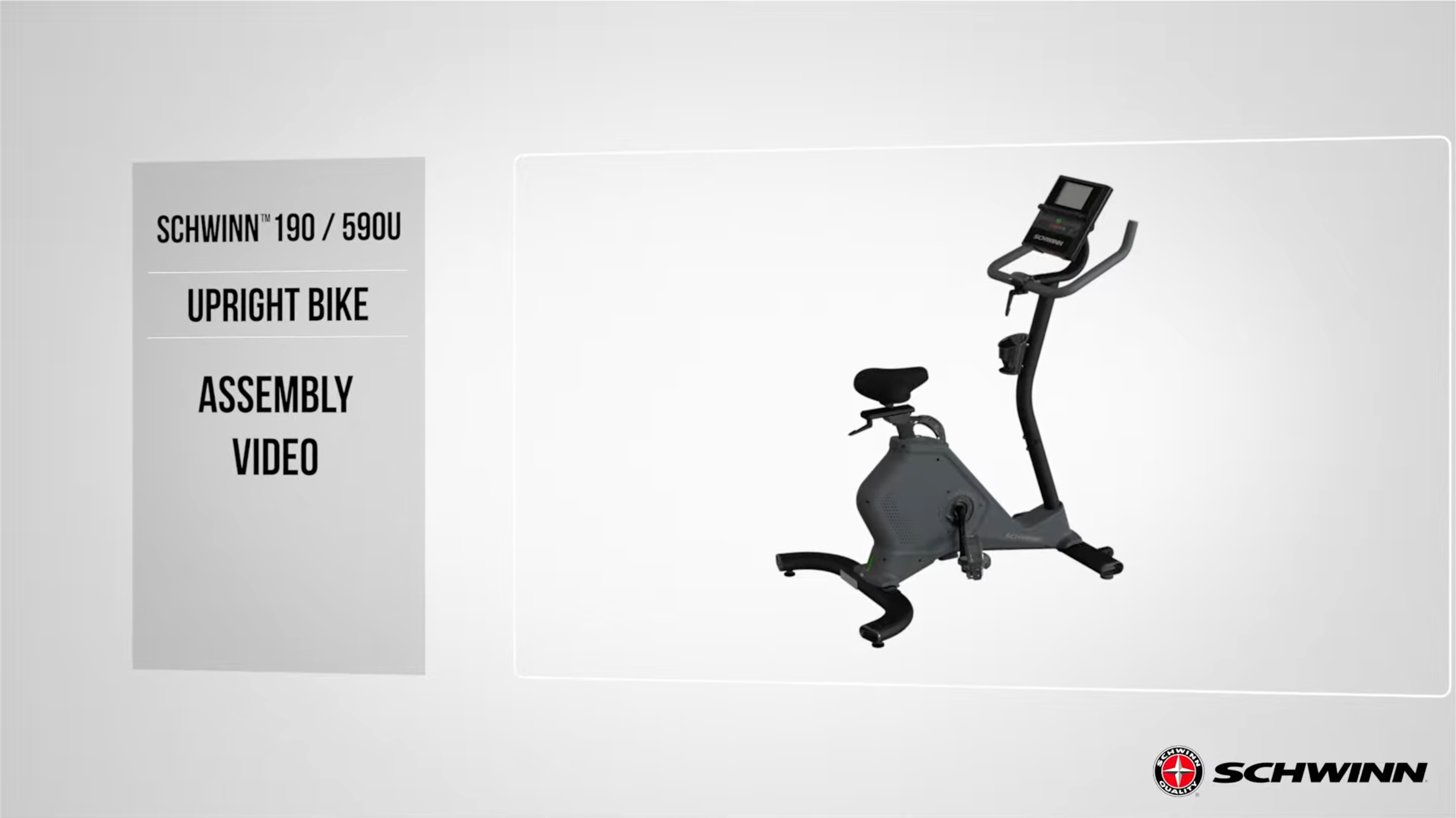
Upright Bikes

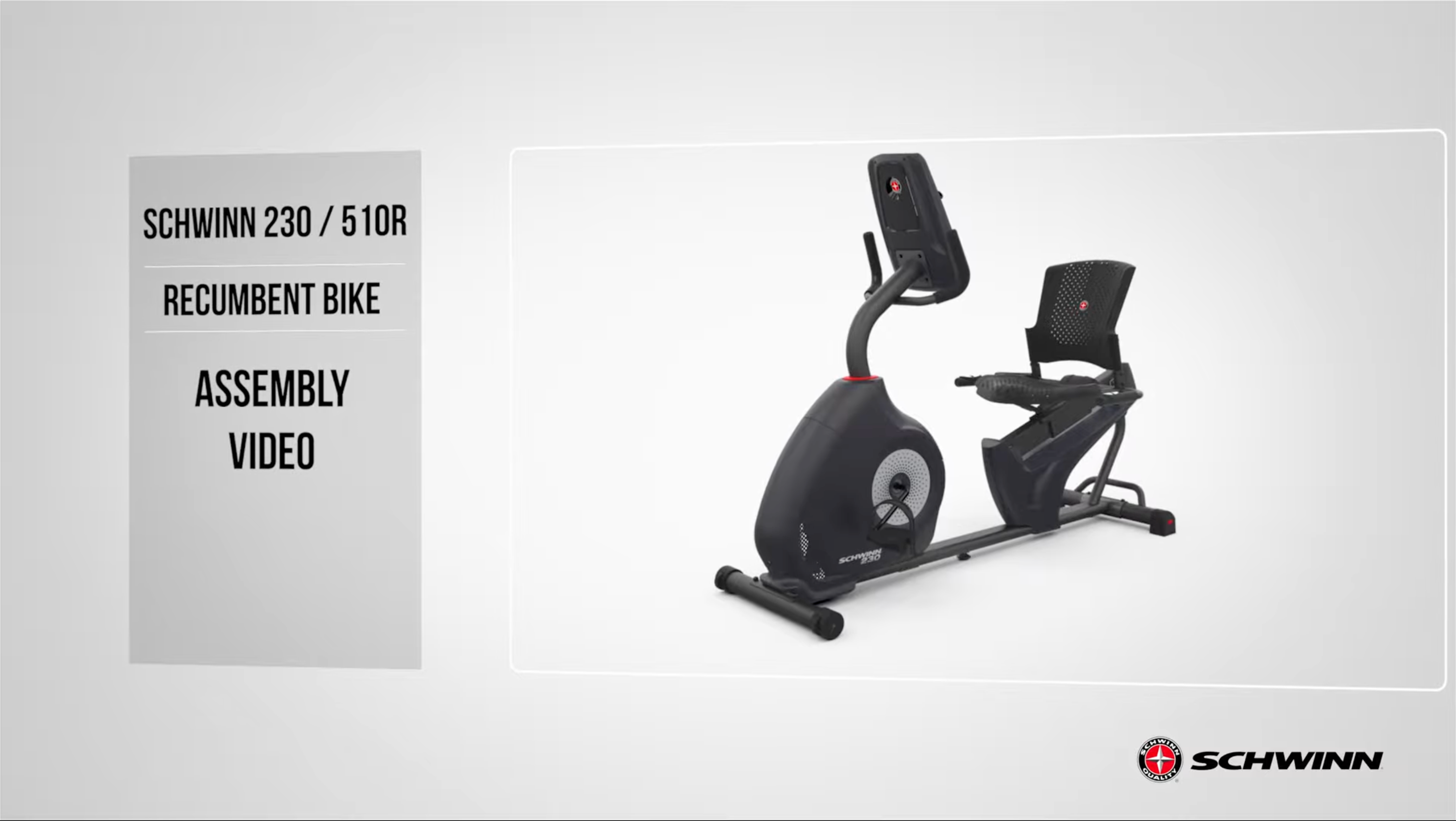
Recumbent Bikes
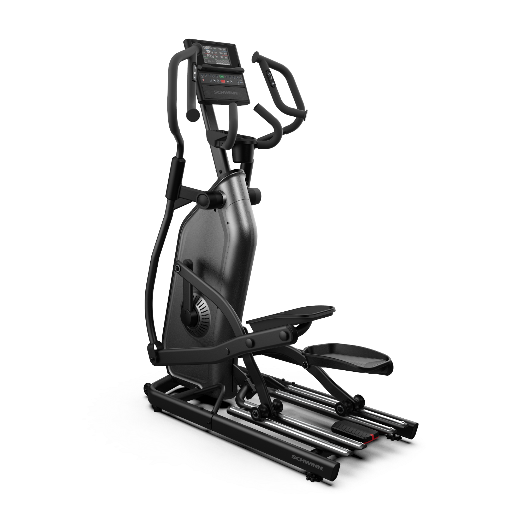
Ellipticals
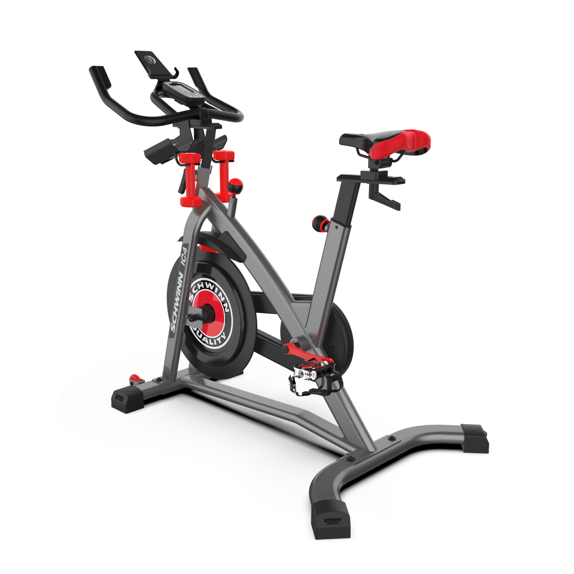
IC4 Indoor Cycling Bike
youtube


Introduction & Preparation
- Safety Setup: Place the bike on a hard, level surface. Ensure a minimum work area of 24 inches around the bike's perimeter [00:11].
- Manual: Read the assembly manual thoroughly for important safety warnings and tips [00:32].
- Assistance: Some steps, such as attaching stabilizers, are heavy and may require two people [00:47].
- Tools Included: #2 Screwdriver, 3mm and 6mm Allen wrenches, and a 15mm/17mm combination wrench [01:16].
Step 1: Attaching the Stabilizers
- Front Stabilizer: Remove pre-installed hardware from the front stabilizer (Part 8) using the 6mm Allen wrench. With assistance, tilt the frame and slide the stabilizer into place. Secure by hand-tightening, then fully tighten with the 6mm Allen wrench [01:31].
- Rear Stabilizer: Remove the hardware from the rear stabilizer (Part 6). Tilt the frame, insert the stabilizer, and secure it by hand before fully tightening with the 6mm Allen wrench [02:21].
Step 2: Attaching the Pedals
- Identification: The left (L) and right (R) pedals/crank arms are side-specific. Remove the grease-protection bags from the crank arms [03:04].
- Installation: Hand-tighten the pedals first to ensure they are straight and avoid stripping threads. The left pedal is reverse-threaded (rotate counter-clockwise to tighten). Once aligned, use the 15mm wrench to fully tighten [03:33].
Step 3: Handlebar Post and Seat Post
- Handlebar Post: Slide the post (Part 2) into the front frame tube, staying below the "stop" mark. Secure it with the adjustment handle (Part C), ensuring it engages a hole and points downward when tightened [05:05].
- Seat Post: Slide the seat post (Part 4) into the frame. Adjust the height using the pull-knob and tighten securely [05:58].
- Seat Assembly: Slide the seat (Part 3) onto the post. Secure it from underneath using the adjustment handle (Part A) and flat washer (Part B). Ensure the handle points rearward when tightened [06:30].
Step 4: Handlebar Assembly
- Installation: Slide the handlebar (Part 13) onto the handlebar post. Secure its horizontal position from underneath using an adjustment handle (Part A) and flat washer (Part B). Ensure the handle points forward when tightened [07:18].
Step 5: Water Bottle Bracket and Holders
- Bracket: Remove the four pre-installed screws from the handlebar. Place the water bottle bracket (Part 12) on top and secure it with the screws using the #2 Phillips screwdriver [08:07].
- Holders: Remove the pre-attached screws from the holders, push them into place on the bracket, and secure them with the screws [08:42].
Step 6: Console Installation
- Mounting: Remove the four screws from the back of the console (Part 1). Mount the console to the handlebar's center bracket and secure it with the screws [09:16].
- Cables: Connect the console cable to the frame cable through the handlebar, ensuring they are fully connected without crimping [09:48].
Step 7: Media Tray
- Installation: Remove the three pre-installed screws from the front of the handlebar. Place the media tray (Part 2) into position and secure it with the screws using the #2 Phillips screwdriver [10:04].
Step 8: AC Adapter & Final Touches
- Power: Plug the AC adapter (Part 9) into the inlet at the bottom front of the main frame and then into a wall outlet [10:54].
- Dumbbells: You may now hang dumbbells on the hooks provided underneath the water bottle holders [11:14].
Final Inspection
- Final Check: Ensure all fasteners are tight and remove protective covers from the console. Check pedals weekly to ensure they remain secure [11:33].
Introduction & Preparation
- Safety Setup: Place the bike on a hard, level surface with at least 24 inches of clearance around the perimeter [00:11].
- Manual: Read the assembly manual thoroughly for safety warnings [00:31].
- Assistance: Some steps may require two people due to the weight of the components [00:45].
- Tools Included: #2 Screwdriver, 6mm Allen wrench, and a 15mm/17mm combination wrench [01:07].
Step 1: Attaching the Stabilizers
- Front Stabilizer: Remove the pre-installed hardware from the front stabilizer (Part 2). Tilt the frame with assistance and slide the stabilizer into place. Secure it by hand-tightening, then use the 6mm Allen wrench to fully tighten [01:32].
- Rear Stabilizer: Repeat the process for the rear stabilizer (Part 3) at the back of the frame, ensuring all screws are tightly secured [02:20].
Step 2: Seat and Seat Post
- Seat Post: Slide the seat post (Part 4) into the frame tube. Do not exceed the "stop" mark. Use the adjustment knob to set the height and tighten securely [03:02].
- Seat Assembly: Slide the seat (Part 5) onto the seat post. Secure it from underneath using the adjustment handle (Part A) and flat washer (Part B). Ensure the handle points rearward when tightened [03:39].
Step 3: Handlebar Assembly
- Handlebar Post: Slide the handlebar (Part 6) into the front frame tube. Secure it with the handle (Part C), making sure it engages the holes and points downward [04:21].
- Handlebar Position: Use the second adjustment handle (Part A) and washer (Part B) underneath the handlebar to secure its horizontal position [05:17].
Step 4: Attaching the Pedals
- Identification: The right (R) and left (L) pedals are specific to each side. The left pedal is reverse threaded (rotate counter-clockwise to tighten) [06:55].
- Installation: Hand-tighten the pedals first to avoid stripping the threads. Once aligned, use the 15mm wrench to fully tighten [06:13].
Step 5: Water Bottle Holder
- Installation: Remove the three pre-installed screws from the handlebar using the #2 Phillips screwdriver. Place the holder (Part 9) onto the handlebar plate and secure it with the screws [07:41].
Step 6: Console Batteries
- Batteries: Open the battery bay on the back of the console (Part 10). Insert two AA batteries, following the positive/negative indicators. Do not mix battery types [08:24].
Step 7: Attaching the Console
- Mounting: Remove the four screws from the back of the console. Mount the console to the center bracket on the handlebar and secure it with the screws [09:02].
- Cables: Connect the console cable to the bike frame cable through the handlebar, being careful not to crimp them [09:42].
Final Inspection
- Check: Perform a final check to ensure all fasteners are tight. Check the pedals weekly to ensure they remain secure [10:04].
Introduction & Preparation
- Safety Setup: Place the bike on a hard, level surface. Ensure a minimum work area of 24 inches around the perimeter of the machine [00:15].
- Manual: Read the assembly manual thoroughly for safety warnings and tips [00:30].
- Assistance: Some steps may require two people as components can be heavy or unwieldy [00:44].
- Tools Included: #2 Screwdriver wrench and a 6mm Allen wrench. Scissors and a box knife are recommended for unboxing [01:17].
Step 1: Attaching the Stabilizers
- Front Stabilizer: Remove the pre-installed hardware from the front stabilizer (Part 2) using the 6mm Allen wrench. Tilt the main frame, align the stabilizer with the bottom holes, and secure it by tightening the screws through the top [01:34].
- Rear Stabilizer: Repeat the process for the rear stabilizer (Part 3) at the back of the bike. Ensure both screws and washers are fully tightened using the 6mm Allen wrench [02:14].
Step 2: Console Mast and Shrouds
- Mast Installation: Slide the console mast (Part 6) through the top shroud (Part 4). Connect the internal cables, ensuring they are not crimped, and slide the mast into the frame tube [02:54].
- Securing Mast: Align the mast with the four side holes on the frame. Use four screws (Part A), lock washers (Part B), and curved washers (Part C) to secure it. Tighten with the 6mm Allen wrench [03:21].
- Shrouds: Lower the upper shroud into place and install the mast gasket (Part 5) to seal the gap between the mast and the frame [03:44].
Step 3: Handlebar Assembly
- Attachment: Place the handlebars (Part 7) onto the bracket on the mast. Adjust to your desired angle and hand-tighten using the T-handle (Part E), flat washer (Part D), and lock washer (Part B) [04:17].
- HR Cable: Use the pull cable in the mast to route the heart rate cable through the slot and to the top of the mast. Fully tighten the T-handle and snap the handlebar mount cover (Part 8) into place [04:43].
Step 4: Console Installation
- Hardware: Remove the four pre-installed screws from the back of the console (Part 9) using the #2 Phillips screwdriver [05:22].
- Connection: Align and lock the cable connectors. Push the excess wire into the mast and secure the console to the mast plate using the four screws [05:35].
Step 5: Seat Post and Seat
- Seat Post: Lower the seat post (Part 10) into the main frame. Do not exceed the "stop" mark. Secure it at your preferred height using the adjustment knob (Part 11) on the right side [06:19].
- Seat: Place the seat (Part 12) onto the post. Ensure it is straight and tighten both nuts (12b) on the seat bracket (12a) using the provided wrench [06:49].
Step 6: Attaching the Pedals
- Identification: Check the "L" and "R" engravings on the pedals and crank arms. Orientation is based on a seated position [07:22].
- Installation: The left pedal is reverse-threaded (rotate counter-clockwise to tighten). Hand-tighten both pedals first to ensure they are straight, then fully secure them with the 15mm wrench. Improper installation can strip the threads [07:45].
Step 7: Final Accessories & Power
- Water Bottle Holder: Remove the pre-installed screws from the console mast post. Align the holder (Part 15) and secure it with the screws using the Phillips screwdriver [09:21].
- AC Adapter: Plug the AC adapter (Part 16) into the power inlet at the bottom front of the main frame [10:02].
Final Inspection
- Check: Ensure all fasteners are tight and the bike is properly assembled. Remove protective covers from the console [10:32].
- Maintenance: Check the pedals weekly to ensure they remain tight. Do not use the bike until it has been fully inspected [10:37].
Introduction & Preparation
- Safety Setup: Place the machine on a hard, level surface. Ensure a minimum workout area of 56 inches by 71 inches with adequate height clearance [00:19].
- Manual: Read the assembly manual thoroughly for important safety warnings and tips [00:12].
- Unboxing: This procedure may require two people. Carefully lift the carton off the machine and check for loose parts [01:08].
- Tools Included: 6mm Allen wrench, Phillips screwdriver, and a 13mm/15mm combination wrench [00:56].
Step 1: Stabilizers
- Rear Stabilizer: Insert and adjust the leveler feet first. Align the center hole of the rear stabilizer with the pin on the main frame bracket. Secure using the pre-installed hardware and the 6mm Allen wrench [02:20].
- Front Stabilizer: Attach the front stabilizer to the front of the frame. Secure with the pre-installed hardware using the 6mm Allen wrench [03:22].
Step 2: Console Mast
- Cable Connection: Connect the console mast cable to the frame cable connector, ensuring the clips lock. Do not pinch the cables [04:16].
- Installation: Slide the mast onto the frame mount. Secure it using the pre-installed hardware and curved washers (ensure they are flush with the tube) using the 6mm Allen wrench [04:31].
Step 3: Handlebars
- Attachment: Open the bracket on the console mast. Place the handlebars inside, adjust to your preferred angle, and close the bracket. Secure by fully tightening the handlebar clamp handle [05:01].
- Cover: Slide the handlebar mount cover down into position over the mount [05:26].
Step 4: Console Assembly
- Mount Bracket: Attach the console mount bracket to the mast using the provided hardware and 6mm Allen wrench [05:45].
- Console: This step requires two people. Tilt the console to hook the top tab into the bracket. Secure the console with the pre-installed screws using a Phillips screwdriver [06:44].
- Cables & Media Tray: Connect the console cables, push excess wire into the mast, and install the pivot cover. Remove the adhesive backing from the media tray and press it firmly onto the console face [07:07].
Step 5: Seat Post and Seat
- Seat Post: Rotate the top shroud aside. Pull the adjustment lever and slide the seat post into the mount (do not exceed the "stop" mark). Secure the bushing with screws and snap the shroud back into place [08:03].
- Seat: Slide the seat onto the post. Ensure it is level and straight, then tighten both nuts on the seat bracket using the 13mm wrench. Tighten the adjustment handle to secure the slider [09:22].
Step 6: Pedals
- Identification: Locate the Left (L) and Right (R) pedals.
- Installation: Note that the left pedal is reverse-threaded (turn counter-clockwise to tighten). Hand-tighten both pedals first to avoid stripping, then fully secure them with the pedal wrench [10:00].
Step 7: Final Accessories & Power
- Water Bottle Holder: Secure the holder to the console mast using the pre-installed screws and a Phillips screwdriver [10:57].
- AC Adapter: Plug the power adapter into the inlet located at the lower back end of the bike [11:25].
Final Inspection
- Check: Verify all fasteners are tight and the machine is correctly assembled before use [11:37].
- Maintenance: Re-tighten all indicated hardware after the first three workouts to ensure smooth operation [11:52].
Introduction & Preparation
- Safety Setup: Place the bike on a hard, level surface. Allow at least 24 inches of clearance around the entire perimeter of the machine [00:15].
- Manual: Read the assembly manual thoroughly for safety warnings and assembly tips [00:30].
- Assistance: Some components are heavy or unwieldy; a second person is recommended for certain steps [00:44].
- Tools Included: #2 Screwdriver wrench, 4mm Allen wrench, and 6mm Allen wrench. You will also need scissors or a box knife [01:17].
Step 1: Attaching the Stabilizers
- Front Stabilizer: Remove the pre-installed screws and washers from the front stabilizer (Part 2). Tilt the main frame, align the holes, and secure the stabilizer using the 6mm Allen wrench [01:32].
- Rear Stabilizer: Repeat the process for the rear stabilizer (Part 3) at the back of the bike. Ensure both screws and washers are fully tightened [02:11].
Step 2: Seat Frame Assembly
- Placement: Lower the seat frame assembly (Part 4) onto the back of the bike frame. Ensure the heart rate cable passes through the frame hole without being crimped [02:54].
- Hardware: Secure the frame plate using four screws (Part A), lock washers (Part D), and flat washers (Part C). Hand-tighten for now [03:20].
- Arm Rails: Secure the side arm rails to the mainframe using two screws (Part B), lock washers (Part G), and flat washers (Part E). Fully tighten these with the 4mm Allen wrench, then go back and tighten the four main frame plate screws with the 6mm Allen wrench [03:37].
- Cables: Connect the heart rate cable to the connector cable from the mainframe [04:06].
Step 3: Seat Pads
- Seat Back: Align the seat back (Part 5) with the rear tubes. Secure it using eight screws (Part B), lock washers (Part G), and flat washers (Part E) — four per side [04:14].
- Seat Bottom: Align the seat bottom (Part 6) with the front holes on the side tubes. Secure from underneath using two screws (Part I), lock washers (Part G), and curved washers (Part H) per side. Tighten with the #2 Phillips screwdriver [04:52].
Step 4: Frame Cover & Adjustment Handle
- Cover: Place the cover (Part 7) over the center bottom area of the seat frame assembly to hide the hardware [05:45].
- Adjustment Handle: Thread the seat adjustment handle (Part 8) into the tube on the right side of the frame. Turn clockwise until firm [06:05].
Step 5: Console Mast
- Preparation: Slide the console mast (Part 9) through the upper shroud (Part 10). Connect the cables from the mast to the mainframe, ensuring they aren't crimped [06:32].
- Installation: Secure the mast to the frame using four screws (Part A), lock washers (Part D), and curved washers (Part J). Tighten with the 6mm Allen wrench, then slide the shroud and shroud cap (Part 11) into place [07:08].
Step 6: Console Installation
- Hardware: Remove the four pre-installed screws from the back of the console (Part 12) [07:54].
- Connection: Connect the cable connectors until they lock. Push the cables into the mast and secure the console to the mast plate using the four screws [08:16].
Step 7: Attaching the Pedals
- Identification: The Left (L) and Right (R) pedals are side-specific. The left pedal is reverse-threaded (rotate counter-clockwise to tighten) [09:07].
- Installation: Start the threads by hand to ensure they are straight and avoid stripping. Once hand-tightened, use the 15mm wrench to fully secure them [09:33].
Step 8: Final Accessories & Power
- Water Bottle Holder: Mount the holder (Part 15) to the left side of the seat frame using two screws (Part F) [10:58].
- AC Adapter: Plug the AC adapter (Part 16) into the power inlet at the bottom front of the mainframe [11:39].
Final Inspection
- Check: Ensure all fasteners are tight and components are correctly assembled. Remove any protective film from the console [12:04].
- Maintenance: Check pedals weekly to ensure they remain secure [12:18].
Introduction & Preparation
- Safety Setup: Place the bike on a hard, level surface. Ensure a minimum workout area of 52 inches by 90 inches with adequate height clearance [00:20].
- Manual: Read the assembly manual thoroughly for safety warnings and tips [00:12].
- Unboxing: This procedure may require two people. Slide the carton upward to lift it off the machine, being careful of loose parts [01:45].
- Tools Recommended: A 6mm Allen wrench, 4mm Allen wrench, Phillips screwdriver, and pedal wrench are used during assembly [00:55].
Step 1: Stabilizers
- Rear Stabilizer: Attach leveler feet to the rear stabilizer first. Align the stabilizer with the bracket at the back of the main assembly and secure it using the pre-installed hardware and a 6mm Allen wrench [02:21].
- Front Stabilizer: Push the front stabilizer into place at the front of the machine. Ensure the center leveler is not too high, then tighten the hardware with the 6mm Allen wrench [03:10].
Step 2: Console Mast
- Cables: Connect the console mast cable to the frame cable connector. Ensure the connectors lock and do not pinch the cables [04:11].
- Installation: Secure the mast to the frame using the pre-installed hardware. Ensure curved washers are flush with the mast tube before tightening with the 6mm Allen wrench [04:25].
Step 3: Handlebars
- Attachment: Remove pre-installed hardware from the handlebar, place it in the bracket at your desired angle, and secure it by tightening the hardware with the 6mm Allen wrench [04:51].
- Mount Cover: Slide the handlebar mount cover into position over the bracket [05:18].
Step 4: Console Mount & Assembly
- Mount Bracket: Attach the console mount bracket to the mast using the pre-installed hardware. Be careful not to pinch the internal cable [05:35].
- Console Installation: This step requires two people. Tilt the console to hook the top tab into the bracket, route the cable through, and secure the console with screws. Connect the cables and push any extra wire into the mast [06:30].
- Media Tray: Remove the adhesive backing and slide the tray tabs into the console slots, pressing firmly to secure [07:22].
Step 5: Seat Assembly
- Seat Pad: Attach the seat pad to the seat frame using the provided hardware and a 6mm Allen wrench [08:07].
- Frame Installation: Attach the support struts and seat frame assembly to the main assembly brackets. Hand-tighten all hardware first, then fully tighten using both 4mm and 6mm Allen wrenches [08:36].
- Seat Back: Remove pre-installed hardware from the seat back, align it with the frame holes, and secure it tightly with the 4mm Allen wrench [10:13].
Step 6: Adjustment Handle & Accessories
- Adjustment Handle: Secure the handle to the bottom of the seat pad bracket using the 4mm Allen wrench [11:00].
- Water Bottle Holder: Attach the cup holder to the seat frame using the pre-installed screws and a Phillips screwdriver [12:35].
Step 7: Pedals
- Identification: Locate the "L" (left) and "R" (right) pedals.
- Installation: Note that the left pedal is reverse-threaded (turn counter-clockwise to tighten). Hand-tighten both pedals first, then fully secure them with the pedal wrench to avoid stripping the threads [11:35].
Step 8: Leveling & Power
- Leveling: Adjust the rear levelers and the middle leveler until the machine is stable on the floor. Tighten the locking nuts to secure the height [13:00].
- Power: Plug the AC adapter into the power inlet located at the lower front of the machine [13:26].
Final Inspection
- Check: Verify all fasteners are tight and the machine performs correctly according to the manual [13:49].
- Maintenance: Re-tighten all indicated hardware after the first three workouts to ensure smooth and quiet operation [14:03].
Introduction & Preparation
- Safety Setup: Place the machine on a hard, level surface. Ensure a minimum workout area of 82.1" x 57.9" with at least 24 inches of clearance for access and emergency dismounts [00:16].
- Manual: Read the assembly manual thoroughly for important safety warnings and assembly tips [00:39].
- Assistance: This procedure may require two people, as some components are heavy or awkward [00:48].
- Tools Included: A ratchet tool and screwdriver are provided. The ratchet direction can be toggled using the directional switch [01:11].
Step 1: Rail and Frame Assembly
- Rail Attachment: Remove hardware from the rail assembly first. Align it with the main assembly and hand-tighten all hardware before fully securing it with the ratchet [03:24].
- Incline Motor: Once the rail is attached, cut the shipping zip ties and connect the incline lift motor arm using the provided hardware [03:51].
- Upright Position: With assistance, pivot the frame assembly into an upright position and remove the shipping blocks from underneath [04:21].
Step 2: Console Mast and Cables
- Mast Installation: Place the console mast onto the frame. Connect the internal cables, ensuring they are not pinched or cut while lowering the mast into place [05:19].
- Secure Mast: Use the four provided "Part A" screws to secure the mast to the frame and tighten fully [05:48].
Step 3: Console Assembly
- Preparation: Remove the pre-installed hardware from the back of the console assembly using the provided screwdriver [06:08].
- Attachment: Place the console onto the mast pivot. Secure it with the hardware and then fully connect the cable connectors, pushing excess cable back into the mast [06:32].
- Pivot Cover: Attach the console pivot cover behind the assembly by pushing it into place until it snaps [07:13].
Step 4: Leg and Pedal Installation
- Legs: Identify the Right (R) and Left (L) legs. Mount the leg to the frame assembly and secure it, ensuring the leg lies straight on the rails [07:34].
- Pedals: Insert the pedal post into the leg and align the pivot pin with the notch on the lower handlebar. The pin should be flush when properly set [08:37].
- Lubrication: Note that some hardware is pre-lubricated; have a cloth ready to wipe away excess [09:07].
Step 5: Upper Handlebars
- Connection: Identify the Right and Left upper handlebars. Connect the internal cables while sliding the upper handlebar into the lower handlebar [10:27].
- Secure: Fasten each handlebar with four screws and push any exposed cables back into the tubes to avoid damage [11:11].
Step 6: Handlebar Covers
- Interior/Exterior: Secure the interior handlebar covers first using the provided screws. Then, snap the exterior covers onto the frame assembly [11:40].
- Inspection: Ensure no cables are being pinched or cut by the covers or screws during this process [11:53].
Step 7: Power and Final Setup
- Power Cord: Connect the power cord to the inlet located at the bottom front of the frame assembly [14:10].
- Maintenance: Apply a small amount of silicone lubricant to the rails to eliminate roller noise [14:55].
Final Inspection
- Verification: Ensure all fasteners are tight and the protective film is removed from the console [14:32].
- Follow-up: Re-tighten all hardware (specifically the rail, incline motor, and mast) after the first three workouts, and then monthly thereafter [15:14].