 800-556-2896


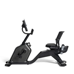


Schwinn 230 Recumbent Bike Assembly Video
In this video, we will show you how to assemble the Schwinn 230 Recumbent Bike!
Begin by Selecting an area where you are going to set up and operate your Bike.
For safe operation, the machine must be located on a hard, level surface.
Please allow a minimum work area of 24 inches around the perimeter of the Bike.
Be sure that the workout space you choose has adequate height clearance, taking into consideration the height of the user, and maximum incline of the fitness Bike.
Before you begin the assembly, please make sure you read the assembly manual thoroughly, as it contains important safety warnings, and assembly tips.
Please note that there are some steps in the assembly process that might require two people to help with the assembly.
Some components of the machine can be heavy or unwieldy. Please use a second person when doing assembly involving these parts.
For assembly assistance, please visit us online or give us a call.
Check the assembly manual for a complete parts list.
Please note that a right (" R "), and left (" L ") decal has been applied to some parts to assist with assembly.
Selected pieces of Hardware have been provided as spares on the Hardware Card. Be aware that there may be remaining Hardware after the proper assembly of your machine.
The following wrenches are included with your assembly: A #2 screwdriver wrench, and a 4mm, and 6mm, Allen Wrench.
A pair of scissors, and a box knife are recommended.
Step 1, Attaching the Front, And Rear Stabilizers.
Begin step 1 by locating the Main Frame, Part 1.
Next, locate the Front Stabilizer, part 2, and place it in front of the Main Frame.
Before attaching the Front stabilizer, remove all hardware.
Remove both screws and washers using the provided 6mm Allen Wrench.
Set the hardware aside for now.
Next, tilt the Main Frame, and matching the front bottom holes, push the Front Stabilizer into place.
Secure the Front Stabilizer using the previously removed hardware.
Insert the Hardware through the top.
Fully Tighten the hardware using the provided 6mm Allen Wrench.
After securing the Front Stabilizer, locate the back-end of the bike.
Locate the rear stabilizer, Part 3 and place it behind the main Frame.
Before attaching the Rear stabilizer, remove all hardware.
Remove both Screws, and washers, using the provided 6mm Allen Wrench.
Set the hardware aside for now.
Next, tilt the Main Frame, and matching the back bottom holes, push the Rear Stabilizer into place.
Secure the Rear Stabilizer using the previously removed hardware.
Insert the Hardware through the top.
Fully Tighten the hardware using the provided 6mm Allen Wrench.
Step 1 is now complete.
Step 2, Attaching the Seat Frame Assembly.
Begin step 2 by locating the Seat Frame Assembly, Part 4.
The Seat Frame Assembly gets attached to the top, back of the bike frame.
The Heart Rate Cable should be facing backwards.
Matching the two attachments, slowly lower and set the Seat Frame Assembly in place.
Ensure the heart rate cable is well-positioned passed through the hole in the frame.
Do not crimp the Heart Rate Cable. Connect the cables once all hardware has been inserted.
Locate the four holes on the Frame Plate, and attach the Seat Frame Assembly using four Part A Screws, Four Part D Lock Washers, and four Part C Flat Washers.
Attach the hardware through the top, and Hand tighten the screws for now.
Next, tighten the seat frame assembly arm rails to the front Main Frame Connections.
Secure the seat frame assembly using two Part B Screws, two Part G Lock Washers, and two Part E Flat Washers.
Fully tighten the hardware using the provided 4mm Allen Wrench.
After securing the front hardware, go back and fully tighten the four screws using the provided 6mm Allen Wrench.
Finally, after all hardware has been tightly secured, go back and connect the heart rate cable with the connector cable from the mainframe.
Step 2 is now complete.
Step 3, Attaching the Seat Pads to the Seat Frame.
Begin step 3 by locating the Seat Back, Part 5, and aligning it with the back tubes of the Seat Frame Assembly.
Matching the holes on the tubes, slowly lower the Seat back into place.
Once in place, secure the Seat Back using Eight Part B Screws, Eight Part G Lock Washers, and Eight Part E Flat Washers, four on each side per tube, as shown.
First, hand tighten the hardware on both sides.
Then, Fully Tighten the hardware using the provided 4mm Allen Wrench.
Fully tighten the hardware on both sides.
Next, locate the Seat Bottom, Part 6, and align it with the front two holes located on the side tubes of the seat frame assembly.
Slowly lower it into place.
Secure the Seat Bottom using two Part I Screws, two Part G Lock Washers, and two, Part H Curved Washers, for each side.
Insert the bolts through the bottom tubes, and into the Seat Bottom.
First, hand tighten the hardware on both sides.
Then, fully tighten the hardware using the provided #2 Phillips Screwdriver.
Fully tighten the hardware on both sides.
After all hardware has been tightly secured, Step 3 is now complete.
Step 4, Attaching the Cover to the Frame Assembly.
Begin step 4 by locating the Cover, Part 7, and placing it over the center-bottom exposed area of the Seat Frame Assembly right underneath the Seat Back.
Slowly lower the cover into place, covering the hardware.
Step 4 is now complete.
Step 5, Attaching the Seat Adjustment Handle.
Begin step 5 by locating the Seat Adjustment Handle, Part 8, and aligning it to the attach it to the tube, located on the right side of the main frame assembly.
Orientation is based if you were to be seated on the Seat, facing forward.
Slowly insert and with a clockwise direction, Hand tighten the Handle until it is firm.
Step 5 is now complete.
Step 6, Attaching the Console mast to the Frame Assembly.
Begin step 6 by locating the Upper Shroud, Part 10, and the Console mast, Part 9.
With some assistance, slide the console Mast through the Upper Shroud, and connect the cables.
Make sure to connect each cable to the appropriate corresponding cable from the Main Frame Assembly. The cables should easily connect.
Take care not to crimp the cables.
After connecting the cables, slide the cables into the tube, and slowly lower the Console Mast.
Make sure the console cable connector does not fall into the console mast.
Slide the console mast down to the frame assembly, until it aligns with the four side holes on the frame tube.
Secure the Console Mast using four Part A Screws, four Part D Lock Washers, and four Part j Curved Washers.
Insert the hardware through the allocated holes, two on the side, and two on the front.
Fully Tighten the hardware using the provided 6mm Allen Wrench.
Next, pull down the upper shroud so that it fits properly on the frame assembly.
Slowly lower into place.
Finally, locate the shroud cap, Part 11, and put it in place so that it seals the space between the console mast, and the frame assembly.
Push it against the Console Mast, and slowly lower it into place.
Step 6 is now complete.
Step 7, Removing the Hardware from the Console.
Begin step 7 by locating the Console, Part 12.
Flip it around, and then remove the four pre-installed screws from its back.
Remove the hardware using the provided #2 Philips screwdriver.
Set the hardware aside for now.
Step 7 is now complete.
Step 8, Attaching the Console to the Frame Assembly.
Begin step eight by locating the Console, and aligning it with the console mast.
Align the clips on the cable connectors, and make sure the connectors lock.
Connect the two cables sticking out behind the console mast, to the cable connections coming out of the Console Mast.
The cables should easily connect.
Push the cables into the Console Mast, and lower the console mast to the console mast tab.
Take care not to crimp the cables.
Once in place, and matching the four bolt holes on the Console Mast Plate, secure the Console using the previously removed hardware.
Fully tighten the hardware using the provided #2 Phillips Screwdriver.
Step 8 is now complete.
Step 9, Attaching the Pedals to the Frame Assembly.
Begin step 9 by placing the Left Pedal, Part 13, on the bottom left side of the main frame.
Be sure to attach the pedals on the proper side of the bike.
Orientation is based from a seated position on the bike.
The left pedal, and the Crank Arm, have an "L" engraved on them While the right pedal and crank arm have an "R" engraved on them.
Please note that the Left Pedal is reverse-threaded, so in order to tighten the Pedal you must rotate it counter-clockwise.
When installing the pedals, it is very important that the pedal is installed straight into the Crank Arms by Hand.
If the pedals aren’t installed straight, the threads that secure the Pedals may strip.
If you feel resistance and the pedal does not turn smoothly into the Crank Arm, then you may remove the Pedal and start again to ensure that the Pedal is aligned correctly.
Try again and tighten the Pedal by hand until you are sure that the Pedal is going straight into the Crank Arm.
After several hand turns, fully tighten the Pedal using the provided Wrench tool.
Keep the Pedal aligned as you fully tighten it with the Wrench.
Once the Left Pedal is secured, repeat these steps for the opposite side and attach the Right Pedal.
The Right Pedal, Part 14, will have an "R" Engraved on it.
Please note that the Left Pedal is reverse-threaded, while the right pedal is regular threaded.
Attach the Pedal.
If you feel resistance and the pedal does not turn smoothly into the Crank Arm, then you may remove the Pedal and start again to ensure that the Pedal is aligned correctly.
Keep the Pedal centered, and aligned while attaching it.
After several hand turns, fully tighten the Pedal using the 15mm Wrench.
If the threads strip due to improper installation, then the Pedals can disengage from the bike and/or break while under usage, which can result in serious injury to the user.
For best performance, periodically check the pedals are properly attached. See the assembly manual for more information.
Once both pedals are tightly secured, step 9 is now complete.
Step 10, Attaching the Water Bottle Holder.
Begin step 10 by locating the Water Bottle Holder, Part 15, and placing it on the left side of the Seat, over the Left Seat Frame Assembly.
Orientation is based if you were to be seated on the Seat, facing forward.
Matching the two holes on the Tube, slowly lower the Water Bottle Holder into place.
Next, secure the Water Bottle Holder using Two, Part F screws
Insert the screws through the top, through the holder and into the frame.
Fully tighten the hardware using the provided #2 Phillips Screwdriver.
Step 10 is now complete.
Step 11, Connecting the AC Adapter to the Frame Assembly.
Begin step 11 by placing the AC Adapter, Part 16, in front of the Main Frame Assembly.
The Adapter gets connected to the Bottom front, of the Main Frame.
Slowly plug in, and fully connect the AC Adapter to the Main Frame.
Please reference the assembly manual for more power related information.
Congratulations! You have now completed the assembly of the Schwinn 230, Recumbent Bike!
Before using the Bike, please make a final inspection.
You may now remove any protective covers from the face of the Console. Please Inspect the Bike to ensure that all fasteners are tight, and components are properly assembled.
Check pedals weekly to ensure they are tight.
Do not use until the Bike has been fully assembled, and inspected for correct performance in accordance with the Assembly Manual.
Please reference the Assembly manual for Workouts, Troubleshooting, and other Program Features.
Enjoy your new Schwinn 230, Recumbent Bike!